|
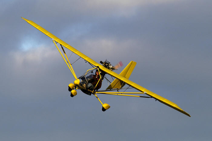
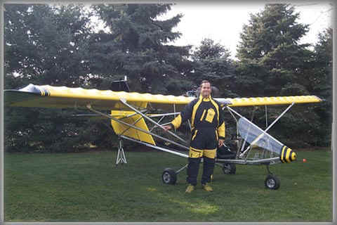
His wife told Aeroworks that "now that
every where we go in their home city; that Max is known as
the guy with the little yellow airplane" (cool ).
He is also an excellent
source of information as he as written a building diary
during the assembly of his Aerosport-103.
Max is also quite active in corresponding with other
Aeroliters.
Building the Aerosport 103
NOTE FROM
BLUEMAX :
It is now 11-16-99
I am preparing
to send this diary to Aeroworks to post to the web-site. My
AeroSport is all done, and I am ready for my first flight.
If you are smart, you will read this entire diary before
beginning your construction. I have thoroughly enjoyed it.
If you are
trying to decide whether to get the slip-on dacron covers,
or the fabric and paint, read that section carefully.
Fabric and paint will at least double your assembly time
(but it's worth it...). I think I've accomplished my goal
with this diary, which is to make the process easier for all
that follow me.
I would
also imagine any builder that came before me could have done
the same thing (and for my sake...why didn't you? You know
who you are...) Enjoy it as much as I have. -Max
DATE HOURS DETAILS
9-16-99
Picked up my
AeroSport 103 kit from AeroWorks in Millersburg, Ohio.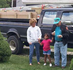
Max's wife,
granddaughter, and Father-in-law. Home and time to assemble
the Aerosport-103!
9-19-99
6.0 hrs
Began
construction. Take the time to make absolutely sure that
the fuselage is level, and square to the vertical tube.
Check, check it again, and then check it again. If it's not
square here, you will be making much more work for yourself
later. Actually, you need to drop what you're doing and go
to Sears. Buy yourself a Craftsman magnetic protractor. It
is about as big as a CD, and a degree scale that you read
through the face. A pendulum swings inside, and is always
plum.
When you put
the base onto whatever you're checking, you simply read the
deviation from plum (that's up-and-down, not to be confused
with level, side-to-side). Since the base rests on the
magnets, and aluminium doesn't work with magnets anyway, you
will want to pry the magnets off and give to your wife for
her refrigerator.
Now the base
will be better. You may also want to order a pneumatic
rivet gun at this point, if you have an air compressor.
You'll need it shortly. I got mine through Northern Tool,
for about $ 60.00. If not, you'll have arms like Charles
Atlas by the time you're done (you young-un's are
saying..."Charles who?")

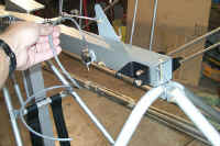
9-20-99 10
Main fuselage assembly
9-21-99 4
Nose gear assembly, adj. to
rudder pedals, windshield.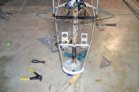
Ordered pneumatic riveter.
9-22-99
3.5 hrs
began setting
ribs on wing - interrupted by curious neighbors.
Get ready for it...once people find out your building an
airplane, you're going to get visitors.
9-23-99
n/a BIG SCREW
UP !!! I realized that the ribs were installed backwards.
Thank God it's only one wing. I ordered 200 new rivets from
a supplier in Cleveland...will be here tomorrow. I don't
need that many, but I'm not done building, either.
In the
meantime, I drilled through all the attached ribs and
removed all ribs. That's the easiest way to remove a
rivet...just use the same size drill bit that you drilled to
install the rivet. Drill right through the center of the
rivet, and it pops right out. I'm in the process of
reattaching them correctly.
The wing is so
symmetrical, I had no way of knowing that the there was
indeed a RIGHT and LEFT wing. AeroWorks said that it has
happened several times, with their builders.
You would think a WARNING in the plans would help??
9-24-99
n/a I'm not
counting this as assembly time, since I had to work
backwards - not forwards. I did get all the ribs turned
around, and encountered no problems. I filled all the old
holes with rivets. I figured the easiest way to attach them
was to put them on the opposite side of the "x" on the line
(which I did). I did get the rivet order today, but still
no air riveter. When I work tomorrow, I'll be picking up
with new work.
Blue
Max NOTE
From this point on, I describe the construction in more
detail. I also tried to make suggestions for improvements.
9-25-99
2.5 hrs.
Attached rib
braces and drilled fabric holes. Mounted aileron tubes.
This LEFT wing is done. Got started with the right wing,
but just barely. I have to work overtime at 12 noon.
9-26-99
7.5 hrs.
I did the
entire right wing in 2:15 ! It sure helps to have done the
first one. When I'm done, it would probably take me half
the time to build another one.
After the
wings, I next mounted the wings to the fuselage, and began
attaching the right side struts. The fuselage has to be
levelled on every axis again. I did this with 2 small floor
jacks under each main gear strut (still no main gear
spindles). This took A LOT of head scratching and
interruptions. USA won Ryder Cup!
The right wing
is ready to have the washout set. The left wing will go
allot faster. I won't be able to work on it tomorrow, as I
am beginning my last concrete job of the year.
10-3-99
8 hrs.
Today I set
the washout on the right wing, attached the left wing and
got it done to this point. I then completed both wings by
attaching the jury struts.
The drawing
shows the l.e. smash rivet using only one, but two on the
rear. It is best to use only one on the rear, also. This
is because the sleeve of the clevis that fits into the jury
strut makes it very tight to get two rivets in. It looks
better with one, too.
HINT:
If you do want to use two, turn the second one 90 degrees.
to the other, which will permit them to fit. I found the
directions on the setting of the washout very confusing.
Here is the
easy way to understand the concept: The objective is to
raise the trailing edge, so the wingtip is at a lesser
angle-of-attack. This way, should you be approaching a
stall, the wingtips will still be flying. You will still
have aileron control (to a point).
Not many
ultralights have washout set in the wings. On the setting
of the washout, I found it much easier to use a magnetic
protractor, instead of a 4 ft. level with a 2" block taped
on. It was very easy to keep going back and
forth...checking and re-checking the angle of attack at the
root and 12" outboard of the strut.
Also, it would
probably be a good idea to have both wings attached before
setting either washout. This is because you may cause the
fuselage level and plumb to change as you lift the trailing
edge of the wing. It would probably be best to have a
helper SIT in the plane (patiently) while you then properly
level the fuselage, and set the washout.
HINT:
A magnetic protractor worked as good and quicker than a
level at levelling and plumbing the fuselage. You can get
one at Sears, as it is made by Craftsman. It has two magnet
strips in its base, but they don't work on aluminium, and
besides, they won't let the thing your checking to make
contact...they only touch the magnet. Get a screwdriver and
pull those magnets out, throw them away.
AeroWorks
claims that the angle of attack should be 5.5 to 6 degrees
at the root, and 4 to 4.5 at the outside of the strut, hence
1.5 ( or 2 ) degrees reduction in the angle of attack. In MY
plane, the angle of attack at the root was exactly 4 degrees
on each wing, so I set the attack angle at the strut at 2
degrees.
I need to
develop a procedure for removing/installing the wings.
Removing the right wing was almost a disaster when the
bungee cord slipped on the ladder, causing the wing to
twist. I think the first step needs to be removing the bolt
that attaches the strut to the lower hoop. Gravity will
hold it in place until you're ready to pull the wing away.
10-4-99
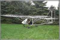
9 hrs.
Well, I
thought I would be able to work on the tail...WITHOUT the
wings on...but I should have looked at a finished photo of
the plane. I would have seen that the upper boom struts
attach to the wings, and everything else attaches to them.
Soooo, the first thing I had to do was put the wings back
on. I am getting the hang of it. I actually put the left
one on without the assistance of a ladder supporting the tip
end. I think it might be easier to do if you don't use
support on the wingtip.
I only made
one mistake. On the " L-tangs" that attach the front of the
horizontal stabilizer to the upper tail boom tube (each
side), I instead used the upper parts of the saddle that
attaches the front horizontal stabilizer strut to the lower
boom tube.
I had mistaken
the upper saddle part(s) for the L-tang, because I couldn't
FIND anything left in the parts that looked like an "L"
except for the upper saddles. I sure could have used a
photo. I am finding that he further I get into assembly,
the less photos showing assembly. They must have gotten
tired of taking photos. I corrected the boo-boo, and
completed the tail assembly.
Everything I
assemble now will be disassembled to do the covering, then
reassembled. I attached all the control horns to the flaps,
ailerons, elevators and rudder.
I ordered a
CITATION 240 HVLP spraying system from Aircraft Spruce &
Specialty Co. I find it sooooo much easier to concentrate
when I'm absolutely all alone, with no kids, radio, noise or
interruptions. I should build it during the night!
10-5-99
3 hrs.
Attached hinges to ailerons and
flaps- attached to wings. In setting the cables for the
ailerons, I found them to be slightly too short. I fixed
this by changing the location of the cable clamp on
 the steering yoke to about 3/4" closer to the steering yoke
itself. The ailerons are now adjusted to droop about 1/2"
from the trailing edge, while the adjusting turnbuckles are
turned all the way in. Perfect.
the steering yoke to about 3/4" closer to the steering yoke
itself. The ailerons are now adjusted to droop about 1/2"
from the trailing edge, while the adjusting turnbuckles are
turned all the way in. Perfect.
10-6-90
4 hrs.
It took a long
time to properly set the flaps. I also attached the
elevators and rudder. I ran out of AN3-13 bolts. I only
need a few more. I also adjusted the flaps to droop (about
1/4").
10-7-99
3.5 hrs
I'm taking
allot of time scratching my head. I attached cables to
rudder and elevators. The cable clamp block next to the
yoke was not in the right place, so I had to unbolt it and
move it 2" towards the seat. It would not allow the yoke to
move past 90 degrees (you couldn't pull it back).
I found out
later from Mark that the block position was okay, but the
actual clamp(s) attached to the block were turned around.
If I had drilled out the rivets and turned it around it
would have accomplished the same thing.
The entire
tail is square, level, plumb, etc. It is as perfect as it
can be. The elevator has more travel up than down, but it
travels the entire limits of the cable. It is sufficient in
each direction, anyway. I think I'm ready to begin
covering!
10-9-99
3 hrs.
I got my
spindles UPS yesterday! They forgot to send me the bolts to
attach them, and the replacement bolts for what was short.
I attached them temporarily by sticking rivets in the holes
(do not squeeze them).
I thought
about toe-ing in the wheels a little bit, but I decided to
follow their instructions...which is straight ahead. The
instructions have you mount the wheels on the spindles, but
the next step attaches the brakes. Obviously, you need to
install the brakes BEFORE you mount the wheels.
I haven't
secured the brake cables to the struts yet, as I will be
attaching the streamlined strut covers. I'm not sure at
this point whether I'll attach them to the outside of the
cover, or drill a hole and run them inside for the most
part. I think this would be a cleaner installation.
They didn't
say so, but you need to put grease on the cable before you
put it in the housing. I need to check out the mounting of
the main strut covers, as holes or slots will need to be cut
for the jury strut attaching points, etc. I also need to
drill the attaching holes for the strobe lights, and
determine were the lines will run. After that, I'll be
taking it back apart so I can begin covering.
10-10-99
3 hrs.
I took it all
apart. I would not want to do this everyday. If it had to
be broken completely down every time I flew, I would hangar
it someplace.
I am very
timid about getting started with the fabric, so I'm going to
wait until tomorrow- when I'm sure I'll not have any
interruptions, as Connie is not here - and I'm watching
Megan while I'm trying to work. That won't work if
something happens and I have to quit.
10-11-99
7 hrs.
I had nothing
to worry about on the fabric. I covered all but the wings.
I tried experimenting with a heat gun, but the heat was too
concentrated, and too hot. It was too easy to get real hot,
real quick. I was able to melt a hole through the fabric
without much trouble. Use an iron instead.
When closing
up the open ends, the manual says to "glue the open end
shut..." I found that the BEST way to do it is to apply
glue over the end where you will be laying the fabric to
close. Apply at the same rate that you did the first two
glue/mek coats before you pulled on the fabric.
With this
layer of glue still wet and sticky, pull the fabric over the
glue and rub it with your finger to seal it. It works very
well, and very quick, and you don't need to clamp it. When
you have the whole side stretched, then cut off the excess
material.
You need to
pull the material at LEAST halfway around the tube (or
whatever). You can use a utility knife to cut off the
material against the tube, but you DO NOT want to cut
against the tube for the other side that you will do next,
as you would also cut through the first layer of fabric.
Instead, use
scissors, and again make sure you are at least halfway over
the end. The fabric should overlap the first layer. After
you've cut the second side excess off, you can smooth the
seam by applying a little more glue.
You can use
the brush to smooth the seam edge, or you can use your
finger (which I prefer). It gets a little messy. If it
feels like it's getting too sticky, you can put a little
more glue on. I thought the hardest part would be cutting
around the clamping blocks on the horizontal stabilizers,
but they were easy. See the photo to see how the
reinforcing patch looks like around the clamping block.
10-12-99
5 hrs.
I finished
putting the straight MEC, then 2 coats of 2-1, MEC-glue mix
over all the perimeter. This took quite a while. I then
heated up a nail set and melted the fabric through at all
hole locations. I took the wings inside and stripped off
the struts and all the hardware. I wiped them clean. I
also drilled the holes for the streamlined strobes. All of
the ribs are still perpendicular.
Tomorrow I
will start with the 2 coats of glue to the perimeter, and go
from there. I also received my EIS by UPS today!
10-13-99
7 hrs.
I got the
right wing glued and covered today, and had begun to shrink
it when the power went off at 5:15 pm in a bad
thunderstorm. The power was off until around 3 am. There
were 26 power outages around the county. The wind blew the
rear lower tail boom over, that I had propped up against
the building. It hit the wheelbarrow and put a dent in the
tube. Not bad- but it ticks me off.
I also found
out that AeroWorks gave me 2 RIGHT wing covers, rather than
one of each. I tried to see if I could use the right cover
on the left wing, but the seams don't line up right. I'm
also running out of glue. I don't think I'll have enough to
finish. I haven't wasted a drop.
I picked up a
Sharp Viewcam at H.H.Gregg for $287.00! I really like it,
and the balance of the project will be in color. Because of
all this, I think I may have to make a trip to Millersburg.
I can pickup the missing landing gear bolt, left wing cover,
and glue. I can return the first instrument. panel, wrong
wing cover, and maybe give them back the instruments that I
will not be using.
10-14-99
7 hrs.
I DID drive
up to AeroWorks. Picked up left wing cover, bolts,
glue...made exchanges. Don't you know that they gave me the
wrong landing gear bolt?? It's too long, and I can't make up
the difference with washers, because they will get in the
way of the strut cover. I'm just going to get a 10/32 die
and thread some more threads on the long bolt, then cut off
the excess. That should work.
Well, let me
tell you...there is alot of work in the wings. I attached
the cover to the left one; glued it; shrunk it; 2-coat glued
it; attached all the reinforcing patches underneath (that
took awhile); and melted the fabric at all hole locations.
Keep in mind I only got as far as beginning to shrink the
fabric on the right wing yesterday, when the power went
out.
I also got the
right wing up to where the left one is. THEN, I put fabric
rivets in one wing. I don't know if I agree with the
"...dip in straight glue..."idea, as this really makes a
mess. I hope the rib tapes cover the glue that has oozed
out around the rivet head. I still need to rivet the other
wing, and then glue on rib tapes to both wings. I should
THEN be ready to UV paint all pieces.
10-15-99
4.5 hrs.
I riveted the
other wing, put rib tapes on both, and applied 2 coats of
glue. The wings are finally ready for UV paint, but the
glue is suppose to dry for 24 hours before UV. I'll paint
the UV on the wings tomorrow. I DID paint one coat of UV on
all the other surfaces.
HINT:
Do your painting outside in the sun, as it dries much
faster. It is latex, of course. I had NO MEK left, and had
to clean my brush out with ACETONE. I suppose it could be
used in place of MEK, but I didn't want to try it.
HINT: When attached the rivets that have been dipped
in glue, do about 12 at a time, then wipe the surface of the
rivet briskly with a terry cloth rag. It rolls up the
excess glue, and is the easiest way to remove it that I have
found.
10-16-99
4.5 hrs.
I applied the
2nd coat of UV to the control surfaces, and put 2 coats on
both wings. I accidentally knocked over the gallon can of
UV! I lost about 1/2 gallon before I could pick it up. As
it turned out, I still had enough UV to do all but about 2/3
of the top of one wing, of the 2nd coat. I need about 8 oz.
to finish. I could not find the UV at ANY paint shop,
aviation shop, etc.
I don't know
where AeroWorks gets it. A guy at Parr Airport in
Zanesville told me that I ought to be able to use latex
exterior (flat black) paint, as it should already have a UV
protectant in it. He is probably right. I've decided that
this is what I'm going to do...NOTHING.
I already have
a good coat of UV on it, and in the manual they discourage
MORE than two coats, as it only adds weight. I'm sure it
will suffer no ill affects of not having a 2nd coat. I'm
ready to scuff the surface with the included ScotchBrite
pad. I will then he ready to paint yellow!
I have to
fully read the instructions that apply to the paint gun,
HVLP, and paint. I also have to build a plastic-enclosed
paint booth.
10-17-99
The weather
was cold and wet today- no painting. I picked up some
polyurethane enamel to practice with. I also need to go to
Ohio Auto Care on Hamilton Rd. tomorrow to pick up the gloss
black paint, and related supplies.
10-18-99
6 hrs.
Today I picked
up the trim paint and assorted supplies. They don't make
Durethane anymore. It was suggested that I use PPG Concept,
instead. I got it is gloss black for the trim. It takes
hardener and reducer just like Durethane. I will also use a
flex additive in it (on the fabric). I got an epoxy primer
to use on the metal. I then came home and built my spray
booth.
Actually, I
just hung plastic around the perimeter. The floor got sticky
as I painted. Let me tell you one thing...I can't stress
this enough...
DO
NOT PAINT WITH THIS PAINT UNLESS YOU HAVE A FORCED AIR
BREATHING APPARATUS!!!
I made the
mistake of taking a breath after I took my mask off, and
before I got out of the enclosure. Whew! It was strong. I
have no doubt that anything less than a separate breathing
source would be dangerous. Thank God the Citation 240 has
the forced air built in.
No about the
painting...I'm not satisfied. First, the mistakes I made:
1) Dragging the bottom of the spray can in the wet paint.
2) Spray gun dripping...fixed when I snugged it down more
securely. 3) Dragging air hose in the wet paint...now I
loop it around my neck- end of problem.
4) It is hard to see the "wet" line of the paint you're
applying.
This could be
remedied by repositioning all of my floodlights so that you
are looking into the glare. It becomes harder to see as you
apply successive coats. I don't know what I'll do about the
finish. I know that the paint seems a little thin, after
adding the reducer. Without the reducer it may cover
better. I'll call AeroWorks at 9 am to see what they say.
I'm not
terribly impressed with the HVLP sprayer, either. Of
course, I did get a full three coats out of it. If would
probably have only covered two using a conventional
sprayer. I think my disappointment with the sprayer is
probably due to the paint viscosity. I DO wonder if it
would not look any worse if I had used a paintbrush...
I'll see how
things go; I may decide to wet sand this finish, and/or
apply a third coat. If I could do it all over again, I
would have applied a white or yellow UV undercoat...NOT
BLACK.
Also, every
little imperfection underneath telegraphed through to the
top. It did seem to get better by the third coat, and
tomorrow, maybe it will be better yet. You MUST take care
of every defect when it happens, or suffer the
consequences. Hairs from the glue brush, excess glue, glue
runs, wrinkled fabric.
If anything
ever happens to this fabric, I'll probably replace it with
that SuperMonokote-type stuff that I saw on the Challenger
at the Fairfield Co Airshow. Oh well, tomorrow's another
day.
10-19-99
I talked to
PPG, and AeroWorks today. PPG said that I should use 1/2 as
much reducer, and that should take care of the problem.
They also said that I should not expect to have complete
coverage with only a tack coat, followed by a wet coat.
They told me to "just paint" with no lighter tack coat.
Todd told me
that the paint is so finely atomized by the HVLP, that may
me causing a problem. They use a Taiwan gun from WalMart
for about $50, and it does a great job. Connie threw the
box away the Citation HVLP came in, so I guess there's no
returning it.
Todd suggested
that I paint over the black UV with a yellow flat latex, as
it's cheaper than using epoxy. I agree. I wish I'd have
never used the UV at all!!! He also said that yellow is the
hardest color to cover. I just got off the phone with Axis
(maker of the Citation 240). He said that I am using the
correct fluid nozzle and needle (1.0 mm).
He also said
DO NOT reduce the reducer, and do everything just as I was.
He said that yellow paint over black is GOING TO TAKE MORE
COATS, and I need to accept that. I guess I agree.
I've just
contacted every paint store in Newark, and no one has an
exterior, flat latex, in yellow, or anything close. I then
went to Meyers, and guess what...they not only had it, but
it was YELLOW. It's a better color than what the Durethane
yellow is! I'll tell you, I think if you could get the same
color in a oil based polyurethane (house paint) I would use
it instead of the Durethane.
I put on 2
coats of the yellow - onto a small area of one of the
elevators. I let it dry completely, then poked and
prodded. I am certain that it will not crack, split, or
peel off. The part that was tested almost completely hides
the black underneath. I think I will now be able to use
only 2 coats of Durethane, and completely hide the black
UV. I can't wait to get started...
10-20-99
9 hrs.
Well...it sort
of covered the black. I did all black UV surfaces with 2
coats. You can certainly still see it is dark underneath,
but maybe it will be enough to only require 2 coats of
Durethane. I could have put it on thicker (easily) but
though it might be asking for trouble, since this latex does
not have a flex agent in it.
I sanded the
previously painted wing, and got it ready for the last coat
of Durethane. I also used a tack rag on it, and will to all
other surfaces prior to painting. The sticky stuff on it
really picks up the dust. I am better at handling and
adjusting the spray gun. The final coat looks pretty good,
and I'm sure the other surfaces will look better yet.
Make sure you
angle the lights to make it easy for you to look into the
glare - it makes it much easier to keep track of your "wet"
line. I really like the LexAire spray gun. The over spray
is greatly reduced. It's also fairly easy to clean.
10-21-99
8 hrs.
I sanded the
2nd wing and painted it. The yellow latex over the black
really made a difference. I only needed two coats of
yellow. Of course, I put the first coat on as a wet coat,
instead of a tack coat. That was the recommendation of PPG.
It was a good one.
After two
coats, I still had enough left to do another side, so I put
a third coat on the bottom. The bottom REALLY looks good.
I then scuff sanded all the rest of the fabric covered
parts. I was careful not to sand too heavily, as it would
sand all of the yellow latex off.
The
consequence of that, however, is that the brush marks can
still be seen under the yellow durethane. There not bad
(and they're better than black streaks), but you can still
see them. When the wing was dry enough, I pulled it out and
laid out all the other pieces., to paint only one side of
them. I leaned them across long sawhorses at about 45
degrees. I was afraid this would cause runs, but I only got
a couple small ones. I put on two coats, with about 30 min.
between coats.
There is
absolutely NO SIGN of the black streaks showing through.
Todd at AeroWorks discouraged me from only doing one side at
a time, but I don't know how I'd have done it otherwise.
Tomorrow I'll
flip them over and finish with two coats...then I'll be
done. I don't think I'll do the black right now, in the
interest of getting it in the air. I'll either do it after
I have flown, or save it for a winter project. I think I'm
going to have a good bit of paint leftover. It's ironic, as
I though in the beginning that I was going to need a good
bit more. I'm leaving both wings outside tonight...I hope
they survive the temperature. (and maybe frost) okay.
10-22-99
Woke up to 20
mph winds, but about 57 degrees. I hope the wings (that
were left outside) survive the wind okay. Okay, I've been
outside. Both wings are OK. The top of the second painted
wing is a bit dull, or satiny. I suppose the temperature.
caused it, except it only got down to about 45 degrees. The
old Simonize reconditioning fluid would probably do the
trick.
I wouldn't
call it oxidized, but it is something similar to the 75
Cutlass that I painted a stripe on the hood. It sort of got
a "foggy" look on the paint surface. I think "blemish" is
what they call it. It looks OK, but I may decide to
re-paint the top. The bottom looks great (of course, it did
get three coats, and the top only got 2).
I painted the
backside of all the other fabric surfaces. They got coats,
and they look okay. I'm going to attempt to wetsand the more
obvious runs, and see what happens. It is taking a long
time for the paint to "cure". I think I am going to do the
black trim ON THE FABRIC ONLY. I'll paint the metal later
on.
I'm going to
keep the trim a simple pattern...well...not too
complicated. I also got the airspeed (0 - 80) today...but
no pitot tube. I'll read up on how to run the tubing.
10-24-99
4 hrs.
I worked on
the instrument panel today. I was going to cover the
existing panel with Formica, but I decided instead to buy a
Formica countertop, and just cut it out. It was mo more
expensive than the smallest sheet of Formica (and I would
have had to buy and apply contact cement).
It is white.
Then...I got the idea to paint it yellow, to match the
plane. This is a great color, and the instruments look
fantastic in it, but...I did it with a brush, and you can
see the contour of the brushstrokes. Not bad...but I'm not
elated with it.
I will now do
one of several things:
1) Leave it as it is;
2) wet sand the yellow flat, then use something to bring
back the gloss;
3) Wet sand it flat, then spray paint it with yellow (and
do the nose of the airplane at the same time;
4) sand off ALL the yellow, and leave it white;
5) Cut out a new one, and leave it white.
Option 3
appeals to me, but I haven't made my decision yet. I wasn't
going to paint the nose of the airplane again, but if I can
find nothing to bring back the gloss, (after wet sanding out
the brush marks on the nose) I will do that. I am also
going to use something to soften the I.P. mount to the
tubing, so as to reduce vibration.
10-25-99
You know, I
got behind on my entries, and I just can't remember what I
did today or the 26th. Sorry.
10-27-99
11 hrs.
I attached
the muffler, minus the elbow hooks welded on. I'll ask my
neighbor if he could weld those on for me. I want to tell
you that properly placing the sleeve around the muffler is
very important. It would be best if you have a helper.
It is
difficult because the position of the muffler changes as you
tighten the bolts around it, relative to its position to the
exhaust elbow. You can take a good look at the photos, and
that might give you a starting point.
You will find
that the muffler slants slightly back towards the engine
when done correctly. This will get the elbow seams lined up
with the exhaust manifold. Realize something else...your
exhaust elbow is held in place to the manifold and the
muffler by springs. The hooks for the springs are already
attached to the muffler and the manifold, but have to be
welded to the elbow.
There will be
three on each side, and should be straight across from the
matching hooks (already attached). The tension applied to
each will not be the same. The elbow will droop somewhat,
as you have the elbow in place, but NOT attached to the
springs.
When
determining where to weld the hooks on the elbow, you will
want to create more of a "stretch" on the spring(s) on the
bottom the elbow, as this will pull the muffler/elbow back
up into perfect alignment. The ball and socket fittings on
the exhaust allow for a pretty out-of-alignment attachment,
but you will want it to be aligned for aesthetic reasons,
too. The MX that I took my lessons in had a horrible
alignment. That made me feel better about my job.
I attached
the elevators, rudder, and the ailerons. I then masked and
painted the black trim. Two coats of BRUSHED on PPG Concept
(black). It is extremely glossy, and levelled quickly.
Maybe too quickly, as a couple of runs developed on the
rudder, as I painted it vertically. It took a long time.
I'd like to repaint my truck with this paint.
10-28-99
7 hrs.
The black
painted tips of the wings look bad. It apparently wasn't
the temperature. that affected them, because all the other
black painted fabric also got cold, but it was inside my
building. (unheated), and all of it looked fine.
I decided to
repaint the wingtips. They do look better, but remember, I
brushed it. It looks great from about 50 ft. I applied a
stripe pattern, using two 1/2 in. stripes and a 2 in.
stripe. It is very nice. I found out by accident that
there is a clear plastic strip that you need to peel off,
after the apply the stripe. The blue masking tape I used
was too sticky. Some of the sticky junk stuck to the yellow
paint, and has proven very difficult to get off. Whatever
gets the goo off, also takes the yellow paint off (like
MEK).
I didn't even
try lacquer thinner, as its characteristics are similar.
But I eventually DID try it, and it seems to work okay,
without dulling of softening the yellow paint.
Here
is the solution.......USE THE 3-M FINE LINE TAPE.
I used a 1/4 in. strip to mask for the black, but then stuck
the blue masking tape to the 3-M tape, but the rest of it
stuck to the yellow paint. If you are going to mask for
spraying, I guess you could use regular masking tape, just
make sure it sticks to the 3-M fine line, and the plastic or
paper that you are masking with.
Your fine line
may need to be about 1/2 in. wide (instead of 1/4 in) to
better accommodate regular masking tape. Also, the fine line
tape made a PERFECT line, and came off easily. The leading
and trailing edges are getting banged up a little bit. I'm
going to need to touch up little marks, maybe after I am
flying.
HINT:
TAKE PRECAUTION TO KEEP ALL PAINTED PARTS INSIDE OVERNIGHT
UNTIL THE COMPLETELY CURE.
As far as I'm
concern, this will take several days, during this time of
year (October). It probably wouldn't be a problem in the
summer.
10-29-99
2.5 hrs.
The wings
survived outside OK. Today I remounted the throttle grip,
so as to provide much more tension when turning the
throttle. I put a screen door spring (about 3 in. long, and
the exact diameter. of the i.d. of the throttle grip) inside
of the throttle grip, between 2 finder washers that I had
leftover. Just push the grip on until it is as much tension
as you want, then tighten down the screws. It works
perfect! Sometimes I just fall in to it.
I also ran the
wires in the wings for the streamlined wingtip strobes. This
was difficult, but I got it done. It would not have been
any easier, had I done it earlier in the construction.
process.
Mounted the
carb., but have not connected any hoses, or the throttle
cable. This is one area where I am critical of the assembly
manual... there are several areas where the clearcut
by-the-numbers procedure is simply not there. It causes me
to waste time, look ahead, etc.
I wish I had
all those hours back... If I didn't have the photos that I
had taken while at AeroWorks, I don't know what I'd have
done. I can't tell you how many times I've walked back
inside to my computer (at least 200) to look at a seemingly
insignificant part of a photo for clarification. Hopefully
for all others after me, what I'm doing will help.
HINT: Do not spill any lacquer
thinner, acetone, or MEK on the LEXAN windshield. It will
melt it, and eventually turn it to mush.
10-30-99
3 hrs.
Today I
attached the strobe heads to the wingtips. This was a real
pain, for a couple of reasons.
1) The male pin that you are suppose to attach to the
wire(s) coming out of the wingtip was too large for the
female coupler already attached to the strobe head. It
absolutely would not fit. This is an inexcusable fault on
the part of Kuntzleman Electronics, and I'm going to tell
them so.
2) Equally inexcusable, the clear lens that attaches
overtop of the blue soft material had the holes drilled in
the wrong place. It would have been impossible to push the
lens far enough onto the strobe so that the hole in the lens
lined up with the threaded hole in the strobe. In fact, it
was far enough off that I had to drill a completely separate
hole on one of the lenses, and both holes on the other. I
hope the rest of the Kuntzleman electronics, that I have not
yet installed, are better quality control.
10-31-99
6 hrs.
I
have to apologize to Kuntzleman.
The fitting on the strobe head is for a stripped wire, not
for the wire in a connector. I read and reread the
directions, and didn't grasp that, but that's because I had
a pre-conceived idea of what they wanted to say. They still
screwed up on the drilling of the holes. I talked to Todd
Raber about it, and he said his Kuntzleman wingtip strobes
were also that way, requiring additional holes to be drilled
in the lens.
Meanwhile, I
attached the prop. This was a piece of cake when I actually
got to doing it. I had to buy a torque wrench that would
measure clear down to 175 in-lbs., which divided by 12, is
the same as 14.58 ft-lbs. The wrench (Craftsman) I had only
went down to 20 ft-lbs.
I also ran all
of the fuel lines, and attached the fuel pump. I don't know
how anyone without a photo of what it's suppose to look like
would ever be able to figure it out. I had taken photos at
AeroWorks, and I've look at them over 200 times. The video
and the photos I took will help immensely.
I mounted the
fuel primer bulb high enough that I could reach it over my
shoulder from the seated position, if I had to. Make sure
you attach the filter and the primer bulb in the right
direction, by using the arrows.
I'm getting a
little aggravated at how long it is taking to get so little
done. It seems that the instructions should be somewhat
more structured, or by the numbers, to tell you exactly
what to do, just like they did in the beginning of frame
assembly. For example, there is nothing to indicate what
line goes where, as it relates to the fuel pump. There are
many other examples.
11-3-99
5 hrs.
Today was a
bad day. Snow flurries all day, cold, blustery. I mounted
the PRECISION POWER SUPPLY and the SMART STROBE DUAL MAGNUM
boxes. I basically mounted the two boxes on top of each
other, like a sandwich.
You'll have to
see the photo. I called Kuntzleman to make sure I was
following the directions right. You have 5 wires coming out
of the Rotax 447:
The brown one
is the ground. Ground this to the frame.
The
half-black/half-yellow wire (by itself) is the ignition kill
wire. Wire this to the kill switch, already attached to the
upper tube. You'll also need to put a small piece of wire
on the other side of the kill switch, and wire it to
ground.
The gray wire
is the tachometer wire. From what I read, this may or may
not be what you use for your tach connection, depending on
what instrument you use. I think with the EIS it will
work. I guess one of the lighting coil wires will also work
for the tach...but only one. If you connect to the tach
using one of these and it doesn't work, then you'll know to
use the other. If you use the tach that came from
AeroWorks, I believe you'll need to use the lighting coil
connection, and tape off the tach wire.
The yellow and
yellow w/black stripe wires are probably clipped together on
a spade bit. These are the lighting coil wires. The power
they produce is AC. Most power-use applications on the
plane require DC, so the AC has to be converted to DC by
means of a regulator/rectifier.
Take these two
yellow wires apart, and connect one of them to the red
stripe/white wire on the smart strobe, and the other to the
black stripe/white wire (on the smart strobe). If you're
not using a strobe system, then the lighting coil wires
connect directly to a rectifier/regulator. The lighting
coil produces AC power, and the rectifier/regulator changes
it to DC power, and regulates the voltage, depending on
rpm.
The Kuntzleman
Precision Power Supply is an elaborate rect./regulator. It
has two wires that need to also connect to the lighting coil
wires (on its input side), and it has two output wires. One
is black, and is grounded. The other is red, and is a 3 amp
DC power supply. It has allot of features, but I won't list
them all here. Any and all of the DC powered accessories
will be powered from this little wire.
In my setup,
that will be the CB radio, the EIS, any landing light(s),
and the DC powered strobe. I don't know how many amps that
all adds up to, but if it's more than 3, something's got to
give. Should it prove too big of a load, I may consider
adding a battery. This would provide an additional source
to draw from for short periods (like when landing with
landing lights, etc.)
It was
suggested by Kuntzleman that I not make the strobes
switchable, that is, just have them on anytime the engine is
running. This seems like a good idea to me. The bulbs are
rated for 1200 hrs., and I did buy them to use them, right?
I will only add a switch if I install a battery, so as not
to draw current when it's not running.
I said it was
a bad day? I was attempting to position my wing behind the
fuselage, so I could plug the strobe into the smart strobe
box, and check the fit. I lost control of the wing, and
ended up dropping it onto the tail boom section. It poked a
hole in the middle top of the fabric. It is more like a
rip, about an inch long. I haven't decided exactly how to
fix it, but I may try SUPER MONOKOTE, then cover it with a
handmade decal, like a bumblebee, stripe, or something like
that. I'm hoping I'll not have to redo it with fabric.
11-4-99
4 hrs.
I have had
some time to thoroughly read the directions for the EIS, and
other related instrument hookups. I connected the EGT
probes to the tapped fittings in the exhaust manifold. Just
screw in the fitting, put the locking nut and compression
fitting onto the probe, and insert the probe tip into the
fitting. Push it in all the way until it touches the other
side of the manifold, then back it out about 1/4".
Tighten down the locking nut, making sure the probe doesn't
slip at you do.
I have read
that you need to remove the rings from the spark plugs, if
you use CHT sending units. I did this. The CHT sending
unit goes over the threaded end of the spark plug, before
you install it. Don't forget to gap the plug, which is
.020". On the Rotax, you can thread the CHT leads through
the cooling fins on the cylinder head, where it will come
out directly over the spark plug hole, then drop the spark
plug into the hole. If you don't, the lead will get bent
up. You'll see what I mean when you examine it.
The photos and
the video both show the proper way. Also, make sure the CHT
ring around the spark plug doesn't start to turn with the
spark plug as you tighten it down. Spray the ring with
WD-40 before you position it.
With all the
various wires that are now accumulating, you need to decide
how they will be run to the various terminations (ie,
instrument panel). It is probably best to leave most of the
wires loose, until you see how many wires you have, where
they go, what can be grouped together, etc. This is where a
picture is worth a thousand words. Study the photos that are
enclosed, and you'll see how I did it, anyway.
11-5-99
4 hrs.
More work on
the wiring today. I cut all the wires coming out of the EIS
that I will not be using. I cut them very short, so they
don't come out of the back of the plug. The EGT and CHT
wires are very long, but all others that need to reach the
engine (ie, tach wire) will have to be spliced, to make them
long enough. I had to pay extra for the pre-wired harness.
I don't know why EIS didn't think that the tach, power, etc.
would not need cables as long as the EGT/CHT.
The entire
frame is grounded, so I found no reason to run the various
ground wires clear back to the upper root tube. I just
grounded things wherever it was convenient. Also, on the
EIS, they indicate cylinders by #1 and #2. Which is
which...you ask? It doesn't matter, so long as you know
which probes are connect to which cylinder, and that one is
designated.
For example,
if you connect the probes from the EIS EGT #1, to the
cylinder closest to the prop, then that is cylinder #1.
Simple enough.
11-6-99
3.5 hrs.
I put all the
wires inside of the black accordion tube, and secured it
with nylon ties alongside of the lower tube and up the
vertical tube. The hardest part of it is trying to
determine how to make the neatest installation. You do,
however, have to know in the beginning where every wire
starts and terminates. And because everything vibrates, I
have taken precaution to isolate wires as best I can. In
the photos, take note of the EGT and CHT leads. All I have
left to do is wire the tail strobe, and install-connect the
Skysports Fuel Probe.
11-7-99
3 hrs.
I forgot
about wiring the remote switches on the EIS. I don't think
I've mentioned this before, but the EIS has three buttons on
the front of it that control its operation. When you are
strapped in, you cannot reach the EIS without releasing your
seatbelt (or at least the shoulder straps). EIS has
attached three leads that you can install on a tube, or
wherever, so that you can control the EIS while strapped.
The switches
are SPST, momentary on. What that means is that when you
push the button it grounds the circuit, which cycles the
display on the EIS. I got mine at Radio Shack. I am
installing mine on the left side of the hoop tube, inside of
a small aluminium box (that I also got at Radio Shack).
There was no
way to attach the switches directly to the tube, as you
could not reach the nut to tighten on the back. With the
box that I bought, there is still room on the front of it to
mount three more push buttons, or a couple of switches
(future devices). I also shrunk on a couple of tubes, where
the wires enter the hole in the tubing. This should keep it
from abrading.
11-8-99
3.5 hrs.
I finished up
soldering the remote wires in the box. I then installed the
throttle cable. Be sure to take all the slack out. Once
you have attached the carb end to its fitting, it's much
easier to the slack out.
My neighbor
welded the exhaust spring hooks onto the exhaust elbow, and
it is perfect. Smear on some Permanex (Loctite) Hi-Temp.
silicone ANTI-SEIZE compound where the elbow touches each
piece.
I had to quit
early, because I drove over to St. Clairsville to take my
first flying lesson. I did very well, and I'm happier than
ever that I bought an ultralight. Something else came to
light, however.
What I am
getting ready to say cannot be understated...
ABSOLUTELY, POSITIVELY, DO NOT EVER EVEN THINK OF TRYING
TO FLY YOUR ULTRALIGHT WITHOUT PROPER TRAINING!!!!!
I got better
very quickly, but when I began trying to bank a turn, it was
not very good. The thing that I learned very quickly is that
making turns is much like changing lanes on the freeway...
movements are very small. There is also a bit of a lag,
after initiating a control.
The takeoffs
and landings were the most fun, as you would expect. Well,
except for the flying about a foot off the ground in the
hayfield, dodging large bales! I'm not kidding! We then
flew at treetop level. I thought the branches were going to
sting my legs. It was more fun than I've ever had on ANY
type of ride. I can't wait to fly my own.
My hearing,
however, did not recover for 1 1/2 days. I had a very
noticeable ringing in my ears. It is the most loud noise,
sustained, that I've ever experienced. We had headsets, and
I don't think it was the engine that was too loud, it was
the volume of the intercom system. I found out later that
my instructor had EARPLUGS, in addition to his headset. I
sure wish I had. I will NEVER to it again! He later told
me that the volume could have been adjusted. I'll use my
own headset the next lesson. If that won't work, then he'll
just have to give me hand signals, because I'm not going
through that again.
11-9-99
Today I
re-read all of the instructions for the Skysports Fuel
Probe. I think I know understand how to install it. I also
put gear oil in the reduction drive. Todd at AeroWorks says
the best way to fill it is to just put 12 oz. in it, rather
than filling it until the oil begins to come out the lower
hole (messy).
I got some
other miscellaneous information from Todd, as follows (in no
particular order):
spark plug gap
is .020"; make sure to remove the spark plug ring, if
installing a CHT probe onto the plug; let your plugs be the
best indicator of how proper mixture and temp. Proper
mixture and temp will produce toasty brown tips.
Too lean
(which also means too hot) will produce light gray or
white, chaulky tips. The proper CHT is 300 to 400 degrees.
You want to be watching it when the temp. gets to 425. He
said for me to set the limit on my EIS to 480 degrees. The
EIS has a red warning light that begins to flash when ANY
parameter has been exceeded.
I guess that
lets you fly, instead of constantly cycling through the
display pages, checking for readings. The EGT limit should
be set at 1200 to 1225. Wide open throttle while flying
should produce 1000 to 1050 degrees. Midrange power will
produce 1100 to 1150.
Funny, isn't
it? You would think that lower rpm would produce lower
temp's. In the box that comes with your Rotax will be a
hardware pack. In it will be two short bolts, with copper
rings. These are the plugs for the EGT fittings on the
exhaust, should you foolishly decide not to install EGT
probe(s).
Incidentally,
there is a hole on each side of the gearbox, that you might
think would need a plug also, to keep the gear lube from
running out (it's also threaded). It apparently does not
need any plug.
Gary Church
(who has some photos on the AeroWorks website) gave me the
following info:
Redline rpm is
6800. Your max rpm, while tied down on the ground
(break-in) should be 6250 to 6300 rpm. You will gain
approx. 300 rpm to your max. power while flying, as you're
now in clean air.
Adjusting
your prop. so that your rpm is too low or too high will
create problems. Your max. power rpm should be about 6500
straight and level.
Also, Todd
told me, without even trying the current setting, to change
the jet needle position. There is a jet needle, and a needle
jet, so don't get confused. The top of the needle has 4
positions, into which a retaining ring is snapped. The
retaining ring controls how far into the needle jet the jet
needle is permitted to drop (or fit). The higher onto the
needle that the retaining clip is positioned, the lower the
needle is permitted to drop into the jet, effectively
leaning the mixture. My ret. clip was in the 2nd from the
top, with a very small o-ring filling the top spot. Todd
had me move it to the 3rd spot from the top (or the 2nd from
the bottom). Reposition the o-ring to the spot vacated by
the ret. clip.
I'll still
need to try it for awhile, to see how it responds. There
seem to be allot of things that control proper mixture:
idle speed, jet needle position, air mixture, etc. I'll go
over the proper start-up procedure, but after I have started
my own. By the way, the "54" on the side of the carb is the
model, not a designation of the size. This carb. is a 36
mm.
11-10-99
4 hrs.
Four hours
today, and not much to show for it. I did get the hole cut
for the fuel probe, but I didn't get it installed. I
connected jumper cables to my truck, to power the EIS, and
set all the parameters before I start the engine. I was
able to power up the EIS, but it wasn't working right. I
traced the problem to the remote switchbox. Specifically,
the "next-ack" button was acting like it was being
depressed, although it wasn't. When I disconnected the
switch, everything worked fine. I removed and re-soldered
the switch, and it worked okay. In a short while, one of
the other two switches did the same thing. I am going to
replace all three switches with better quality switches from
somewhere else.
11-11-99
4 hrs.
Four lost
hours again. I tested the EGT and CHT probes, with heat.
The EGT leads proved to be attached backwards. In other
words, the cylinder that I had designated as #1 was reading
as #2 on the EIS. All I had to do to correct it was to cut
off the heat-shrink tubing and disconnect the spade bits,
then switch them. The CHT probes were fine.
The
instructions for the calibrating of the fuel probe are
complicated, but complete. What I want to accomplish is to
have the gauge read "empty" when there is actually a gallon
of fuel left. I can also calibrate it so that it reads in
percent. ie, when the tank is full, it will read 100%. At
one actual gallon, it will read 0%. I got rushed at the end
of my allotted time, so I didn't get the probe secured in
the tank. I did put exactly one gallon of fuel in the
tank. I also had to cut the probe (it started at 24"). So
it would fit in the tank w/o hitting the bottom. I think
the probe is now 14 to 14 1/4". I accidentally dropped the
internal flange into the tank (I knew it would eventually
happen). I'll try and retrieve it with a magnet.
I also picked
up three new switches from AutoZone. They are automotive
type, and heavier construction. They won't have to be
soldered, as they have spade-type connectors. They are also
lever-type, rather than push-button. I may like them
better. The instructions to installing and calibrating the
fuel probe are very complicated. I am not at this point,
going to go into the step-by-step. I'll come back to it
after it's all done and add something.
11-12-99
4 hrs.
Success
today. I got the fuel probe attached, and I was successful
in calibrating it the way that I wanted. I was not,
however, able to do it without almost completely draining
the tank. It is required in the directions, but I thought I
was more clever than that, and tried to do it without it.
It cannot be done that way, because the adjustment "pots" on
top of the fuel probe are tied in to each other. When you
turn either one, the display on the EIS changes. If anyone
has any problem calibrating theirs, just give me a call.
I'll be glad to help.
It won't do
for me to go through the entire procedure here, as they will
all be different. I took the day off from work today so I
could go back to St. Clairsville and take my second lesson.
The earplugs and the volume control made all the difference
in the world. I could almost here him better with a headset
than if we were face to face.
We practiced
cross-controlling, stalls, and of course, takeoffs and
landings. It was pretty windy, but more than that, it was
gusty. I understand now why so many ultralight pilots do
not like to fly in the wind. You are in a constant state of
correction. I hadn't thought of it, until now...but I had
always wondered whether I would get airsick or not. I've
read some about it, and I guess it is influenced by your
mental state, as well as the physical factors. I'm happy to
say that I have not even remotely gotten sick to my
stomach. I would think it would have happened today, if it
were going to happen. Now I've probably jinxed myself.
11-13-99
4 hrs.
Boy, I can
taste it now! I'm so close. I just have trivial details to
finish up. I safety wired the prop (a total of ten bolts),
the reduction drive (two fill plugs on side, top and bottom
plugs), the exhaust springs (6), the muffler-to-cylinder
head bolts (2), and the fuel probe (5). Don't forget to put
Loctite on the muffler-to-cyl. head bolts. This is probably
pretty important, as you cannot tighten down the bolts too
tight. What I mean is that it won't let you, as the rubber
washers begin to squeeze out long before it gets tight.
Neither the
fuel probe or the propeller came with safety wire, so I ran
out on the fuel probe. I'll get some before I fly. I also
found the solution to the little slit I put in the top of
the right wing. I found a roll of (believe it or not)
BRIGHT YELLOW Super Monokote, from my model airplane days.
It is not quite as "yellow" as the durethane paint, but it
was pretty close. I ironed it on in three layers,
increasing diameter ovals. It worked perfect! It also
shrinks up, just like the fabric.
This is what I
have left to do:
1) put graphite lube on the throttle and brake cables
2) mount tail strobe
3) reassemble
4) mount my GPS
5) break the engine in.
One of our
patrol pilots from the aviation section told me I need to
check the weight and balance. He said that AeroWorks should
have something to indicate where the Center of Gravity
should be. I'll have to contact them on that. I would also
like to weigh it, so see what the gross weight actually is
(with and without my weight added).
11-14-99
6 hrs.
I started my
engine!! It was fantastic. I feel such a sense of
fulfillment. You know, if any of the wiring, mechanical
connections, fuel system, prop bolts, or a dozen other
things had not been right, then it might not have started.
I am proud of myself. There...I'm reaching around and
patting my own back.
I didn't break
it in, as it was pitch dark by the time I was able to start
it. I can't believe how long it took to put it back
together. I still need to attach the tail strobe and the
gap seals. The right side wingtip strobe didn't work. The
left one worked intermittently. I am positive it's because
the replacement connector pins I used were too large in
diameter, and I couldn't shove them up into the connectors
far enough. The circuit could not be completed. I'll
replace them with the proper ones tomorrow.
I had a
pleasant surprise...the EIS is backlit (green) and it is
bright! It seemed to function fine, in the short time the
engine was running. I let the CHT climb to 225 before I
revved it at all. I didn't go over 4500 rpm, and that was
just for a couple of seconds. I can't wait till tomorrow to
break it in.
HINT: When starting the engine, prop the tail up onto
something, just as when you're assembling the tail. I
didn't make this mistake, but I'm sure that if you leave the
tail on the ground, it will come up hard on it's nose gear
when you apply throttle.
Incidentally, I rotated the brake drums 90 degrees.
forward. This put the brake cables more on top, rather than
coming up from underneath. Had I left the cables
underneath, they could snag tall grass, etc. Now if you
have already attached your brake cables the way I had
originally done it, then you didn't read through this entire
diary before you started construction! I have to make
corrections as I go, you should be doing everything right
the first time, at my expense!!
Remember when
I described putting the ribs on backwards? I had another
builder email me, and he indicated that he was getting ready
to do his wings. Before I could warn him about the rib
problem, he had already begun attaching them backwards. I
believe he only did 4 or 5 that way, then he saw the holes
for the hinges on the leading edge, and realized he had them
backwards.
 |
|
Max Rentz standing by his AEROSPORT-103
while wearing an OZEE Flightsuit with
matching color scheme to his Aerosport-103 (
nice- touch ). |
I took the
opportunity, since I had the brake assemblies loose, to
correct a slight binding in each brake drum. This was
caused because the large washer (paint black) that has been
welded on the spindle was not exactly perpendicular. This
washer is the part that you drill through, in order to
attach the brake assemblies. I took a quarter size washer,
cut it in half, and shimmed between the two in order to make
it perpendicular.
The wheel and
brake drum can then be attached, and the wheel spins freely
without rubbing on the shoes. You can tell if you have the
same problem by seeing if the spacing between the drum (on
the wheel) and the brake shoe plate is even. If not, then
you'll need to shim it, too.
You know, I
haven't added up all the hours, but all I know is I have
really enjoyed the building process. I once heard a house
builder say, by the time he finishes a house...he hates it.
I understand where he's coming from. I thought I would run
into that here, but I couldn't have been farther from the
truth. I will have an empty feeling when all the
construction process is done. I guess that will give me
reason to add things, or tweak.
I do still
have to paint and install the streamlined strut covers, CB
radio, etc. That also gives me hope for the future, as I
one day will be building a homebuilt airplane, such as a
Velocity or a Lancair. Can't wait till tomorrow...
11-15-99
3.5 hrs.
Well, it's
tomorrow! Lots of fun today. I spent a couple of hours
rounding up miscellaneous parts: Galvanized wire (safety
wire, 20 ga.); a keyed switch to use in the ignition
circuit; graphite for the throttle cable; tie down anchors;
and while attempting to get new connector pins for the tip
strobes- I actually found identical connectors- pins and
all!! The package was at an old electronics store, and
looked like it had been hanging there for 20 years. It had
yellowed, and the price was written in pencil. No bar codes
here! I connected them all, and attached the tail strobe
also. No need to run the ground wire clear up to the rear
mast, just put it on an "eye" connector and attach it to the
bolt that holds the strobe on.
Remember, the
whole airframe is grounded. Okay, now for the results on
the engine break-in. Everything went fine, although it
takes 1 hour, 4 3/4 minutes. During this time, I got cold-
as the prop was pulling air. I guess that's better than
being behind it.
I followed
AeroWorks instructions, which is as follows:
1) Fuel on
2) Choke on
3) Squeeze primer bulb
4)Ignition on (or kill switch off, whichever terminology you
prefer) 5) yell "CLEAR PROP"!!
6) pull the starter rope. A couple of pulls, and it will
fire.
Unlike most
other engines, it will run, albeit a little rough, with the
full choke on. Let this run for about 30 sec. to 1 minute,
then kill the engine. Walk around the plane and take the
choke off.
Come back
around, ignition on, "clear prop", and pull starter rope.
If yours is like mine, you'll have to keep it at about 2500
rpm to keep it from dying. It is a brand new engine, and it
will run better as it breaks in. By the time I was done
with my break in, mine idled at 2230 rpm, and was very
smooth. There was no hint of quitting.
Below is the
ROTAX 447 break-in procedure. I recommend making a copy of
this, as I did, and keep it on a clipboard where you are
sitting (and you will be sitting). I took my Rolex off, and
put on my Casio w/stopwatch. That way, all you have to do
is keep track of the total time, and where you're suppose to
be. I put a checkmark alongside each duration as I finished
it. I also noted the average EGT and CHT as I
progressed. I didn't think of doing this until I was well
into it, however. The numbers are in italics-bold.
|
RPM |
DURATION (min.) |
RUNNING TOTAL
(min.) |
EGT |
CHT |
|
2000 (idle) |
2 min. |
2 min. |
|
|
|
3500 |
5 |
7 |
|
|
|
5000 |
1 |
8 |
|
|
|
2000 |
1 |
9 |
|
|
|
4000 |
5 |
14 |
|
|
|
5500 |
1 |
15 |
|
|
|
2000 |
1 |
16 |
|
|
|
4500 |
5 |
21 |
|
|
|
Max (6250) |
10sec |
21:10 |
|
|
|
2000 |
1 |
22:10 |
|
|
|
5000 |
5 |
2710 |
1100 |
345 |
|
Max (6280) |
15 sec |
27:25 |
|
|
|
2000(2250) |
1 |
28:25 |
1020 |
301 |
|
5000 |
5 |
33:25 |
1092 |
337 |
|
Max (6310) |
20 sec. |
33:45 |
996 |
378 |
|
2000 (2210) |
1 |
34:45 |
1027 |
318 |
|
5000 |
5 |
39:45 |
1009 |
331 |
|
Max (6330) |
30 sec |
40:15 |
1000 |
376 |
|
2000 (2220) |
1 |
41:15 |
1027 |
310 |
|
5500 |
5 |
46:15 |
1070 |
360 |
|
4000 |
5 |
51:15 |
1170 |
320 |
|
Max (6370) |
1 |
52:15 |
1050 |
360 |
|
2000(22700 |
1 |
53:15 |
970 |
296 |
|
Max (6340) |
2 |
55:15 |
1000 |
379 |
|
2000 (2270) |
1 |
56:15 |
980 |
320 |
|
5500 |
5 |
61:15 |
1100 |
370 |
|
Max (6280) |
3 |
64:15 |
1050 |
430 |
|
2000 (2230) |
30 sec |
64:45 |
975 |
280 |
I also listed
the rpm at max throttle and idle. I have not touched the
idle or air adjustment. I only moved the jet needle to the
3rd position, as a stated earlier. I was told that there is
a midrange rpm where the engine seems to get hot, and that
did happen.
As I recall,
it was at 4500, which was from 16 min. to 21 min. (check the
chart). Slower or faster, it was okay, but 4500 caused the
EGT to read about 1235 to 1240. I'm sure it won't be a
problem in the air. My alarm on the EIS is set at 1225
degrees. I'm going to reset the alarm limit to 1200, as
that is the published limit from Rotax. I may lower it from
there, depending on what I find out from those that know.
The published CHT limit from Rotax is 480 degrees. The
highest CHT I read was 441, and that was at the very end of
the last full power segment which lasted 3 minutes. I told
you that AeroWorks told me to set the EIS warning to 480?
Well, the whole purpose of the alarm is to give you warning
before it's a serious problem. I'm going to reduce that
parameter also, probably to around 420 or so. Hell, it only
reaches about 1000 degrees. at max throttle.
As you can
see, I'm getting over 6300 rpm average at full power. That
will probably translate into over 6500 in the air. We will
see... The idle speed is very constant, at 2230 +/-
average.
I'm going to
have to create more spring tension on the throttle handle,
though. It wanted to return to idle when I let go of it.
Remember the screen door spring in the handle? All I need
to do is push it on a little tighter.
Okay, I
couldn't resist...I had to get in and taxi across my back
yard. I could only go about 60 feet (with the trees and
all) but it was neat. I found I was also able to start it
from my strapped in position. Now to wait for a warmer
day...
Time
to Reflect...
I am now ready
to fly. I have a couple of little details to complete, and
I will continue to add to this diary as I prepare for and
complete the first flight.
The whole
purpose of this was to help you build your AeroLite -
AeroSport, by clarifying the directions, having an abundance
of photos to use as reference, and little hints that will
speed up your assembly. The most important function of this
diary is to keep you from making MISTAKES, like I did.
Remember the wing ribs?
Some of the
text will not apply to your plane (ie, if you don't install
an EIS). I spent alot of time on the strobes, EIS, and fuel
probe. Those that opt for these accessories will appreciate
it...all others...just skip that part!
From time to
time, I have been critical of AeroWorks. You will agree,
however, that I never questioned the quality or integrity of
a component or assembly. I found not a single remarkable
flaw in the kit, as supplied. Thank God that what they may
lack in assembly manual expertise, they make up in their
skill where it counts.
I have no
experience with other ultralight manufacturers, but I have
seen some of their kits. Some of the devices cause me
concern. Remember, I had originally planned to get a
two-place, probably a Challenger. I was so impressed by the
AeroLite I changed my mind, knowing that I was giving up a
seat.
You will also
get excellent phone support from AeroWorks. You may get a
recording when you call, but they will call you back the
same day. You can also call me at (740) 366-2176, or email
me at
bluemax229@netscape.net .
One more thing...I'm not an English major. I write for
substance, not sentence structure. My goal is to articulate
building procedures, and little more. Don't email me,
saying that I ended the sentence of page 13 with a
preposition. I do spell pretty well, though, and I seldom
need the spell checker. If you find a mistake, it is from
the typing. I did go back and edit certain areas, as I
learned more information about the topic, etc. Some of the
writing may seem not to "flow" as well, as a result.
It's been two
months to the day that I picked up my kit from AeroWorks. I
do wonder how much less time it would have taken if I had
done these things differently:
1) No written diary, photos, or video
2) Dacron slip-on covers, rather than the time-consuming
fabric and paint
3) no EIS (including fuel probe)
4) eliminate wingtip and tail strobes
5) eliminate the black UV underpaint (only applies to
fabric)
6) eliminate the head scratching...hours and hours of
staring at the instructions.
I just counted
up the hours...207 grand total. You're now
thinking...that's alot more than the "60 to 80" advertised,
but remember all the extras listed above.
I'm absolutely
certain that I could have built a Dacron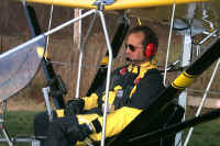 version in 60 hours, without all the accessories. With what
I have learned, I'm also certain that I could do another one
in about 40 hours.
version in 60 hours, without all the accessories. With what
I have learned, I'm also certain that I could do another one
in about 40 hours.
Enjoy your
construction, and safe flying!! -Max P. Rentz
(aka- "BlueMax")
Ultralight
News Editor's note: The following note from the factory
was received when I asked for permission to use the story on
site.
One thing to keep in mind is while Max did a great job in
putting his diary together. He had never built or flown any
aircraft before this . He also did many modifications to his
plane drastically extending the build time along the
complexity of the original design.
However he does say it would be twice as easy this time
around and feels he would follow more of our ( factory )
recommendations during assembly. We have also really updated
our construction manual ( which was pretty good compared to
most ) with a newer and even better one.
Max is one of my favorite owners and is very active in
communicating with fellow Aeroliters. We at AERO-WORKS
really enjoy him very much. You may want to contact him and
I know Max may want to do an update to add to this building
diary as his experiences of flying an what he as learned
from this. Contact Max @ Max P.Rentz
E-mail Address(es):
bluemax@voyager.net
Thanks Todd |